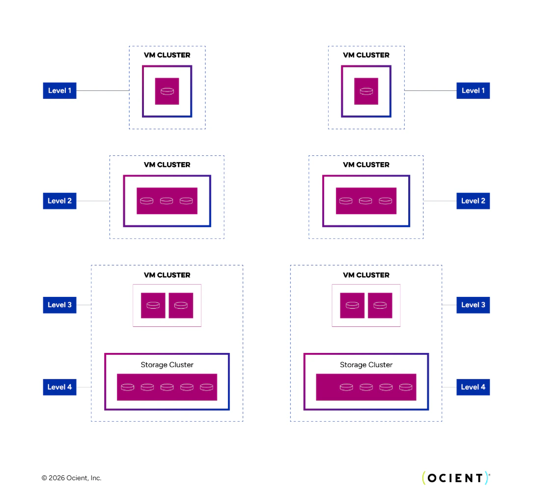
Cluster of Clusters
Various system components in have each been designed to scale not only with hardware capabilities as technology progresses, but also in number of nodes storing and processing data. Like any distributed system, issues of fault tolerance, availability, and communication all become increasingly challenging as the number of units increases. The Ocient scalability approach can be broadly described as deriving from clusters of clusters: smaller, locally connected clusters that manage their own availability and local state independently and without consideration to any other clusters in the system. The design goal of this is to minimize global state and global synchronization in any aspect of query processing, fault management, data loading, or data ownership. There are different kinds of clusters: metadata clusters, storage clusters, VM clusters, and loading clusters. An Ocient deployment can contain zero of more of each. With respect to scalability, each cluster runs its own Raft-based consensus protocol and maintains its own local shared state with it. Individual nodes can belong to multiple clusters and participate in multiple disjoint consensus protocols at the same time, but system scalability derives from the fact that no node has any global view of system state, and indeed, no such global state exists. This allows Ocient to quantify the upper bound on theN parameter described in the erasure coding section. Recall that N is the number of segments in a segment group. In a storage cluster, segment ownership and availability is confined to and maintained in the cluster-local consensus protocol. A necessary implication of data management rules for atomic (but still local) state changes is that a particular segment group must be stored entirely within one storage cluster. And because the Ocient System cannot place two segments from the same group onto the same node, the value N cannot exceed the number of nodes in a target storage cluster. This finally means that the upper bound on N is the practical limit on the consensus protocol implementation, coupled with the design goal of not allowing clusters to be “too big”: somewhere in the range of 20 - 40, depending on deployment and schema details.
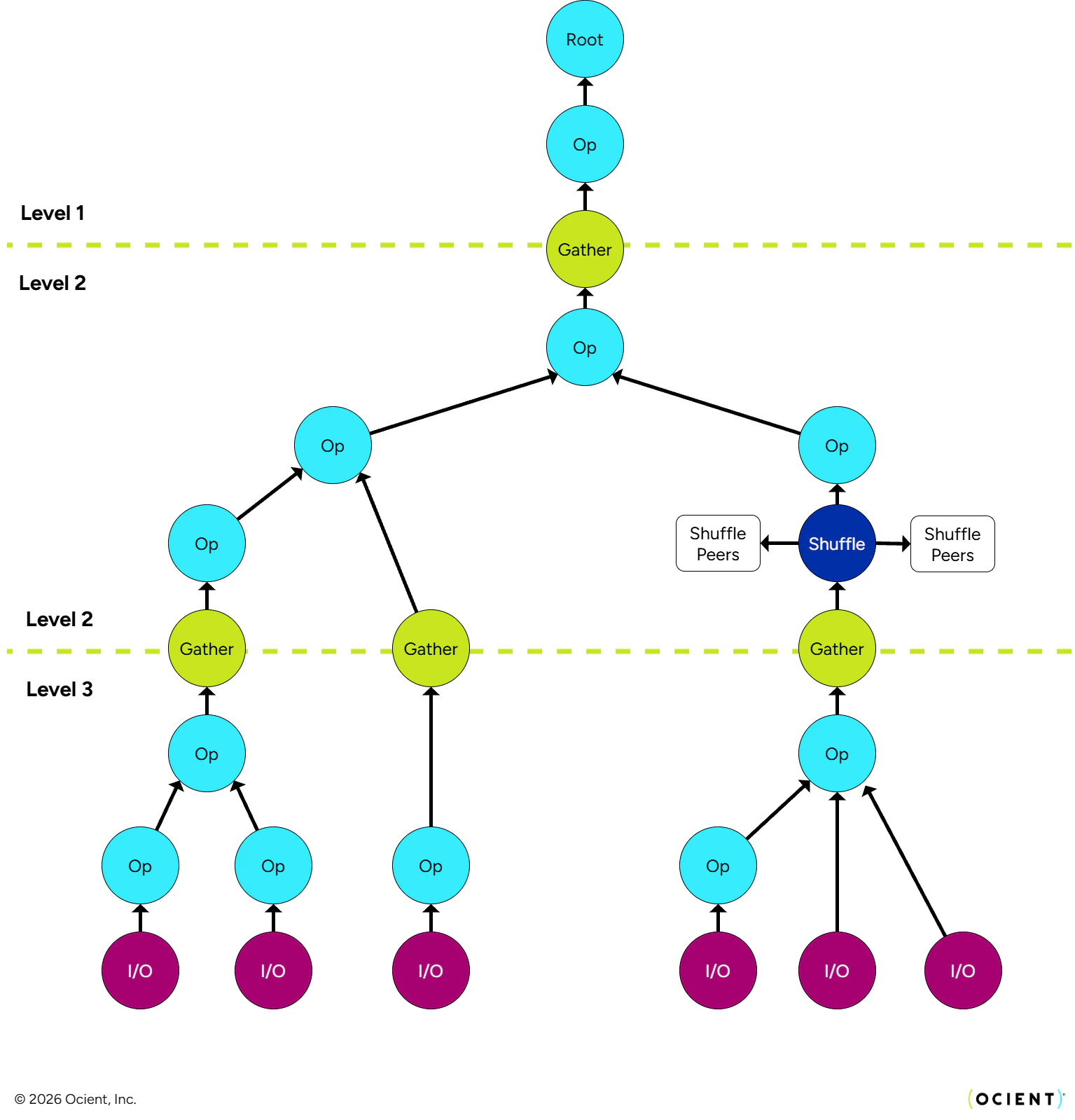
Query Trees (and Plan Trees)
Query execution necessarily spans multiple VM and storage clusters. A key phase of query processing, prior to any actual computation is the query probe, which establishes the query tree to be used for that particular query. This tree fixes, for the particular execution with which it is associated, the set of nodes that provide which segments across all storage clusters, as well as the set of nodes that co-participate in the distributed execution of the query. The former is important because, as nodes and drives come and go, and as new data is loaded and old data is removed, it is imperative that all segments that should be included in a query are actually included exactly one time. The latter is important because each node might need to know exactly which subset of peers in the network are performing which aspects of query execution. In both cases, the probe phase enables query execution to proceed without any global coordination or synchronization. This graphic shows a query execution tree, which can scale up by increasing the number of clusters (represented horizontally in the graphic).